Installation & Guidance
Installation, termination & deployment guidance for Hyperspan™
Hyperspan™ is installed using standard Cat6 tools, connectors, and termination methods—no specialist equipment required. This page is designed to help installers, integrators, and engineers apply sound installation practice, reduce avoidable failures, and validate performance properly on extended-reach deployments.
01
What this covers
What this covers
Handling, routing, bend control, termination quality, channel design, PoE loading, testing, and common field issues.
What this is not
This guidance supports good practice, but it does not replace formal standards, project specifications, or site-specific design review.
When validation matters most
Always validate thoroughly on longer links, high-power PoE runs, critical CCTV paths, outdoor routes, and interference-prone environments.
Core principle
On extended runs, the installation quality often matters just as much as the cable itself—especially connectors, patch points, and real load conditions.
1) Installation overview
Hyperspan is designed to work with familiar structured cabling methods. The goal is not to introduce complexity, but to apply disciplined installation practice so the extended-reach benefits are preserved end-to-end.
Use standard tools
Use Cat6-rated connectors, keystones, patch panels, and normal termination tools. No proprietary hardware is required for basic installation.
Keep topology simple
For best performance, minimise unnecessary interconnects, patch points, and transitional hardware. Cleaner channels usually give better outcomes.
Validate real-world operation
Where distance or PoE demand is high, final acceptance should reflect real device operation—not just a quick continuity check.
Best practice mindset: treat extended-reach deployments like precision installs. Small weaknesses in terminations, patching, or cable handling that might go unnoticed on short runs can become the limiting factor on long ones.
02
Cable handling & routing
Correct handling protects electrical performance and reduces mechanical damage. Avoid installation shortcuts that introduce crush points, tight radius bends, or excessive stress.
Key handling rules
- Avoid tight bends or kinks during installation
- Do not crush cable under fixings, trays, lids, or building elements
- Maintain sensible separation from mains power where practical
- Use appropriate containment and support over the full route
- Pull steadily and avoid aggressive jerking or snagging
- Inspect the route before termination, not only after
1. Plan the route first
Check transitions, containment, bends, and penetrations before pulling the cable.
2. Protect the cable path
Use proper support and avoid leaving cable exposed where it may be crushed, snagged, or impacted.
3. Re-check before handover
Visually inspect the route for sharp bends, trapped sections, poor dressing, and obvious interference risks.
| Handling check | What to aim for |
|---|---|
| Bend control | No tight radius bends, no kinks, no forced turns around sharp edges. |
| Pulling practice | Steady, controlled pulling with no sudden snatching. |
| Route protection | Use suitable containment, support, and segregation from risk areas. |
| Interference awareness | Avoid close parallel routing with power where practical, especially over distance. |
| Final inspection | Check the full route before termination and again before sign-off. |
03
Termination guidance
On extended-reach links, termination quality can be one of the biggest performance variables. Good terminations reduce uncertainty and help preserve the cable’s intended behaviour across the full channel.
- Use Cat6-rated connectors, keystones, couplers and patch panels
- Keep pair untwist to an absolute minimum
- Maintain consistent conductor order to T568A or T568B end-to-end
- Use quality components—poor hardware can undermine a good cable run
- Dress and secure cable cleanly at the termination point
- Re-terminate anything that looks doubtful
| Do | Don't |
|---|---|
| Use reputable Cat6-rated connectors and jacks | Use cheap, inconsistent, or poor-fit components |
| Keep pair twists tight until the last practical point | Untwist excessively before punchdown or plug termination |
| Match the same wiring standard at both ends | Mix T568A and T568B accidentally |
| Inspect conductor seating and strain relief | Assume a first termination is automatically good |
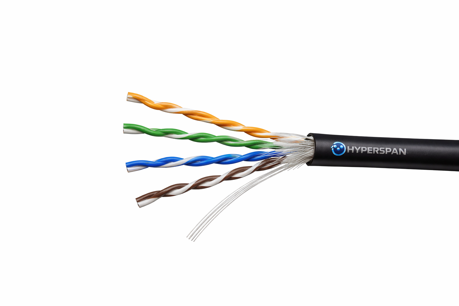
Use Cat6-rated components and maintain pair integrity as close to the point of termination as possible.
04
Channel design best practice
Extended-reach results depend on the full channel, not just the cable length. Every patch lead, coupler, socket, panel, and connector adds variables. Simpler channels are usually stronger channels.
Reduce interconnects
Where possible, reduce unnecessary patch points, transition points, and couplers. Each connection adds insertion loss and risk.
Keep patch leads sensible
Use good-quality Cat6 patch leads and avoid excessive patching on already challenging longer links.
Design for the real endpoint
Think beyond distance alone: device NIC tolerance, PoE demand, environment, and expected operating conditions all matter.
Practical rule: if the deployment is near the upper limits of the intended design, make the channel simpler before trying to “test your way” through avoidable complexity.
05
PoE deployment guidance
PoE performance is not only about whether power is present—it is about whether the endpoint remains stable under real operating load.
Validate PoE under load
- Test the final device connected at the far end
- Check operation under peak demand, not idle only
- Consider night mode, heaters, PTZ movement, IR, radios, or startup spikes
- Confirm switch or injector budget matches the actual endpoint profile
Examples of “high-load” states: CCTV camera IR at night, PTZ movement, heater activation, dual-radio Wi-Fi load, smart devices booting, or environmental changes that increase draw.
| PoE check | What to confirm |
|---|---|
| Power source | Switch or injector is appropriate for the endpoint and the planned distance. |
| Device mode | Test in the highest realistic operating state, not just a bench idle condition. |
| Stability | Watch for restarts, brownout symptoms, intermittent behaviour, or degraded function. |
| Channel simplicity | Where PoE margin is critical, remove unnecessary channel complexity first. |
06
Testing & commissioning
Acceptance should reflect the intended use of the link. For long runs and important deployments, passing traffic and supporting the endpoint reliably under real conditions matters more than a superficial check.
Physical checks
Confirm route quality, termination integrity, connector seating, and that no visible mechanical damage has been introduced during installation.
Link checks
Confirm stable link negotiation, expected speed, and clean operation over the intended duration—not just momentary sync.
Service checks
Validate the actual endpoint function: video stream, Wi-Fi service, control traffic, PoE stability, and sustained operation over time.
Important: on longer or more demanding links, “works on first plug-in” is not the same as a robust sign-off. Always allow for meaningful runtime and realistic load where project risk is material.
07
Troubleshooting common issues
| Symptom | Likely causes |
|---|---|
| No link | Incorrect termination, wiring mismatch, damaged connector, failed patch lead, damaged route section. |
| Intermittent link | Poor punchdown, marginal connector seating, mechanical stress, environmental movement, poor patching. |
| Device powers but behaves badly | PoE budget issue, peak load instability, brownout under demand, injector or switch mismatch. |
| Unexpected performance limit | Too many interconnects, patch lead quality, poor terminations, noisy route, endpoint limitations. |
Fast troubleshooting sequence
- Re-check both terminations carefully
- Swap patch leads with known-good Cat6 leads
- Inspect for crushed or sharply bent sections
- Remove unnecessary couplers or patch points
- Test with the real endpoint under real load
- Compare behaviour with an alternate injector or switch port if needed
08
Final commissioning checklist
Route
- ☐ Path inspected
- ☐ No tight bends or crush points
- ☐ Containment and support complete
Termination
- ☐ Cat6-rated components used
- ☐ Twist maintained close to contacts
- ☐ T568A/B consistent end-to-end
Operation
- ☐ Stable link confirmed
- ☐ Endpoint tested under load
- ☐ Project notes documented
Need help with a real deployment?
Share your run length, topology, device model, and PoE type and we’ll help you assess the best Hyperspan approach for the job.